
PEXGOL PIPES: DESIGN CONSIDERATIONS
Defining the design temperature
The design temperature of the Pexgol pipe is chosen according to data from the RFI questionnaire.
- Buried pipes: according to the temperature of the liquid flowing through the pipe
- Exposed pipes: design temperature calculated by adding 20°C to the maximum ambient temperature (for example, a design temperature of 60°C for maximum ambient temperature of 40°C).
- Alternatively, according to the temperature of the liquid flowing through the pipe (if higher than 60°C)
Water and Newtonian fluids
The pipe class is selected according to the following data from the RFI questionnaire:
- Pressure head losses in the line expressed in bars (taking into account the specific gravity of the transported material).
- Design temperature.
- Basic safety factor (design coefficient):
- 25 for water and fluids with the classification A in the chemical resistance list.
- For materials with classification B, C, D in the chemical resistance list, please consult us.
- 5 for air supply lines
- Static pressure according to the altitude difference in the line and the specific gravity of the transported material.
- If the pipeline is horizontal and the static pressure is low, select class 6 and verify its suitability.
- Choose a higher class with the same OD in order in to increase the transportable section lengths.
- The hydraulic calculation usually results in the same OD.
- If the altitude difference in the line is significant, select a Pexgol pipe class that has in the design temperature higher pressure rating than the static pressure. The additional pressure margin is used for the pressure head losses; this will determine the ID of the pipe.
- The OD is determined by the Pexgol pipe class the customer chooses and the availability of this specific pipe diameter.
Replacing waterline steel pipes
When replacing steel pipes (Hazen-Williams C=110) with Pexgol pipes (Hazen-Williams C=155) with the same pressure head losses, the ID of the Pexgol pipe can be 88% of the ID of the existing steel pipe.
When replacing steel pipes with Pexgol pipes with the same ID, the head losses are expected to be lower by 50%.
Influence of temperature changes on Pexgol pipes
- Pexgol pipes placed above the ground or over bridges tend to get longer (to expand) when temperature rises (snaking phenomenon) or to get shorter (contract) as the temperature decreases. Expansion or contraction does not affect the Pexgol pipe, even in extremely low temperatures.
- There is no need to protect the pipe against thermal stresses, as they are absorbed by the pipe.
- Fixpoints or guiding clamps are used for restraining the elongation of the pipe (mainly for aesthetic considerations).
- There is no need for installation of “expansion joints” or omegas.
- Special fixpoint clamps should be used before and after the fittings (as recommended) to prevent the pipe from pulling out.
Pexgol pipes above ground
Pexgol pipes withstand exposure to sunlight for unlimited periods—that is, the lifetime of the pipe. They can be placed directly on ground and special bedding is not required.
Pipes under full vacuum conditions, the minimum pipe class is 15.
Pexgol pipes at low temperatures
Pexgol pipes are used at temperatures as low as -50°C and even lower. Since the Pexgol material does not become fragile at these temperatures, it tolerates bending and dragging at low temperatures during installation.
Pexgol pipes tolerate complete “homogeneous” freezing of the transported liquid. Homogeneous freezing takes place if the pipe is evenly exposed to low temperatures along the pipeline. However, if freezing starts at localized freezing points, the pressure of the fluid which is trapped between two adjacent freezing points increases until the pipe bursts (this happens to any pipe material). Localized freezing points might be metal fittings (including Pex-lined steel fittings), fixpoint clamps or any point where the metal touches the pipe. Consequently, localized freezing points should be avoided or properly insulated. Please note that this applies to both above-ground and shallow underground installations.
Slurry Design Considerations
The pipe class is determined based on the following data from the RFI Application Questionnaire:
- Working pressure
- Design temperature
- Chemical resistance of the pipe material to the slurry
The pipe diameter is chosen based on the ID of existing steel pipe or on the value of the minimum critical slurry velocity.
When replacing carbon steel slurry pipes with Pexgol pipes with the same ID: a slurry pipeline is designed according to the minimum critical velocity of the slurry material. Carbon steel slurry pipes can be replaced with Pexgol pipes of the same or slightly smaller nominal ID, maintaining the same slurry velocity. The following table can be used as guidelines for choosing the suitable Pexgol pipes for replacing carbon steel slurry pipes according to the ID and flanges of existing steel pipe. The values of the ID of the Pexgol pipes in Table 39.1 are nominal ID values which were calculated based on the value of the nominal wall thickness of the pipe. The Pexgol pipes were chosen assuming that the working conditions of the existing steel pipes are appropriate for the Pexgol pipe classes listed here. Pexgol special reducers should be used for matching ID of Pexgol pipes to existing steel pipes.
| Sch. 40 Carbon steel pipe | Pipe | Loose flanges | Pipe | Loose flanges | |
|---|---|---|---|---|---|
| Size | ID | ||||
| 3” | 78 | 90 class 15 | 3” | 110 class 24 | 4” |
| 3 1/2” | 90 | 110 class 15 | 4” | 125 class 24 | 4” |
| 4” | 102 | 125 class 15 | 4” | 140 class 24 | 5” or 6” |
| 5” | 128 | 160 class 15 | 6” | 180 class 24 | 6” |
| 6” | 154 | 180 class 15 | 6” | 200 class 24 | 8” |
| 8” | 202 | 250 class 15 | 10” | 280 class 24 | 10” |
| 10” | 254 | 315 class 15 | 12” | 355 class 24 | 14” |
| 12” | 303 | 366 class 12 | 14” | – | – |
| 14” | 333 | 400 class 15 | 16” | 450 class 24 | 18” |
| 16” | 381 | 450 class 12 | 18” | – | – |
| 18” | 428 | 500 class 12 | 20” | – | – |
Abrasion allowance
Pexgol pipes have an “abrasion allowance” of 20% of the nominal wall thickness of the pipe. This means that the pipe can withstand the design working pressure until the remaining wall thickness of the pipe is reduced to 80% of the nominal value. The real lifetime of the pipe depends on the actual abrasion rate in the line. The 80% rule applies for all working pressures and all temperatures in all classes.
Increasing the ID of the Pexgol pipes due to abrasion results in decreasing the velocity of the slurry. In order to make sure that the value of the minimum critical slurry velocity is maintained after 20% abrasion, the ID of the Pexgol pipe can be calculated by multiplying the Nominal Pexgol pipe ID by the correction factors in the following table.
| Pipe | Correction Factor |
|---|---|
| 6 | 1.016 |
| 8 | 1.021 |
| 10 | 1.028 |
| 12 | 1.0345 |
| 15 | 1.044 |
| 19 | 1.057 |
| 24 | 1.074 |
| 30 | 1.1 |
Design considerations for Inclined and Dewatering Pipes, High-Gradient Supply Lines
Design considerations
All these type of pipes should be axially restrained at the top and bottom of the line.
The pump rests on the ground. The weight of the pump and water column is not supported by the pipe.
Defining the design temperature
The design temperature of the Pexgol pipe is chosen according to data from the RFI questionnaire.
- Buried pipes: according to the temperature of the liquid flowing through the pipe.
- Exposed pipes: design temperature calculated by adding 20°C to the maximum occurring ambient temperature (e.g. a design temperature of 60°C for an ambient temperature of up to 40°C).
Selecting the Pexgol pipe for dewatering/uphill pipes
Design example:
- Required flow rate: 150 cubic meters per hour
- Pipeline goes from an altitude of 2100 m to an altitude of 2235 m
- Line length: 500 m ambient temperature 40°C
- The pipe can be installed above ground or covered by 0.9 m of soil
Calculate the line pressure by grade line calculation or according to any other applicable method.
Calculate the static pressure at the lowest point of the pipeline taking into account the fluid density. For water, divide the altitude difference (in meters) in the line by 10. The result is in bar. Please note that the lowest point is not necessarily at the bottom of the pipeline.
In this example, 2235 – 1100 = 135 m = 13.5 bar
Choose the appropriate Pexgol pipe class from allowable working pressure table by looking at the design temperature.
Select the Pexgol pipe class which has a higher working pressure than the calculated value in section. The additional pressure margin will be used for the head losses.
Design temperature for above ground installation is
40° + 20° = 60°C
Selected pipe class for buried pipes installation:
Class 19 | Working pressure: 14.9 bar | Temperature: 40°C
Selected pipe class for above ground installation:
Class 24 | Working pressure: 15 bar | Temperature: 60°C
Alternative pipe: Class 30 | Working pressure: 18.9 bar | Temperature: 60°C.
Design temperature for buried pipes is 40°C.
Alternative pipe – class 24. Working pressure – 18.7 bar at 40°C
Calculate the pressure margin and the allowable head losses coefficient J.
Pressure margin for above ground installation is:
15 – 13.5 = 1.5 bar= 15 m J= 15 x 100 / 500 = 3%
Pressure margin for the alternative pipe for above ground installation is:
18.9 – 13.5 = 5.4 bar = 54 m J= 54 x 100 / 500 = 10.8%
Pressure margin for buried pipes installation is:
14.9 – 13.5 = 1.4 bar = 14m J= 14 x 100 / 500 =2.8%
Pressure margin for the alternative pipe for buried pipes installation is:
18.7 – 13.5 = 5.2 bar = 52 m J= 52 x 100 / 500 = 10.4%
Select the pipe diameter according to the calculated J and the flow rate.
- The selected pipe diameter for above ground installation is 200 class 24.
- The alternative pipe diameter for above ground installation is 180 class 30.
- The selected pipe diameter for buried pipe installation is 200 class 19.
- The alternative pipe diameter for buried pipe installation is 160 class 24.
Advantages of the alternative pipe: Smaller diameter that allows transportation of longer pipe sections = cheaper transportation. Plus, cheaper pipe per meter length.
Disadvantage: higher head losses.
The line designer should include in the line the all the required accessories including air relief valves and drain valves.
If the overall altitude difference in the line is much higher than the maximum allowable altitude difference H of the highest Pexgol class available, the line should be designed using booster pumps.
Selecting the Pexgol pipe for a downhill pipeline using a full cross-section flow design.
In a full cross-section flow design the pipe has to support the full static pressure (liquid column) of the line.
Design example:
- The pipeline goes down a slope from an altitude of 2250 m to an altitude of 2100 m
- Required flow rate: 150 cubic meters per hour
- Line length: 1500 m
- Ambient temperature: 40°C
- The pipe can be installed above ground or covered by 0.9m of soil
Calculate the line pressure by grade line calculation or according to any other method.
Calculate the static pressure at the lowest point of the pipeline taking into account the fluid density. For water – divide the altitude difference (in meters) in the line by 10. The result is in bar.
Please note that the lowest point is not necessarily at the bottom of the pipeline.
In this example the lowest point in the line is located at the end of the line:
2250 – 1100 = 150 m = 15.0 bar
Choose the suitable Pexgol pipe class from allowable working pressure table by looking at the design temperature. Select the Pexgol pipe class which has the same or slightly higher working pressure than the calculated value in section
Design temperature for above ground installation is:
40 + 20 = 60°C
Selected pipe class for above ground installation:
For a full cross-section flow design the pipe should be Pexgol Class 24 in order to allow a working pressure of 15 bar at 60°C
Calculate the allowable head-losses coefficient J based on the altitude difference in the line and the line length:
Altitude difference is 150 m
J= 150 x 100 / 1500 = 10%
For a full cross-section flow design, select the suitable pipe that can transport the required flow with the calculated value of J.
- Selected pipe class for above ground installation is 160 class 24.
- Selected pipe class for buried pipe installation is 160 class 19.
Check the value of the expected surge pressure (water hammer) against the maximum permissible total occasional pressure, which is 2.5 the working pressure in the design temperature.
For the 160 class 24, the Line velocity V= 4 m / sec
According to the surge pressures table the surge pressure for class 24 is 3 bar for V=1m / sec. for V=4m/sec the surge pressure value will be 4×3=12 bar. The total occasional pressure will be 15+12=27 bar.
The maximum permissible total occasional pressure in Class 24 at 60°C is 15×2.5=37.5 bar.
Conclusion:
The 160 class 24 is OK or the 160 class 19, the line velocity V=3.44m/sec.
According to the surge pressures table, the surge pressure for class 24 is 3.2 bar for V=1m/sec so for
V=3.44 m/sec the surge pressure value will be 3.44×3.2=11 bar. The total occasional pressure will be 15+11=26 bar. The maximum permissible total occasional pressure in Class 19 at 40°C is 14.9×2.5=37.25 bar.
Conclusion:
The 160 class 19 is OK
Air relief valves
Air relief valves are required in any pipeline material including Pexgol. The line designer should include in the line the all the required accessories including air relief valves and drain valves.
As a service to our customers, Pexgol application engineers can perform the analysis of the line in cooperation with A.R.I. Israel and supply a drawing with the location of the air relief valves. Pexgol supplies the air relief valves and the saddles/fittings required for connecting the line accessories to the Pexgol pipes.
The following data is required for the analysis:
- List of key points along the line in Excel file or PDF/DWG drawing of the line with the following details:
- Name of the point.
- Location of the point – distance from the beginning of the line and height above a reference point.
- Type and functionality of each fitting: drain, cut-off valve, pressure reducer, outlet connection to consumer (indicate flow rate), etc.
- Working conditions:
- Flow direction
- Discharge rate
- Inlet/outlet pressures
Selecting the Pexgol pipe for downhill single slope pipeline using a partially filled cross-section flow design
Please note that this type of design requires a skilled designer so the following information should be considered as guidelines only.
In case of a partially filled cross-section flow design, the pipe is to be designed so that it will be in a low pressure (close to an atmospheric pressure) in all or most of its length. This design allows the use of a lower pipe class of with a larger OD and this might be problematic for transportation.
Calculate the allowable head losses coefficient J based on the altitude difference in the line and the line length.
Calculate the ID of the pipeline (according to Hazen –Williams C=155 or any other formula). In order to make sure that flow regime will be a partially filled cross-section, the selected actual ID of the line should be at least 25% higher than the calculated pipe ID.
Selecting the Pexgol pipe class: It is a good practice to design Class 15 in order to allow full vacuum resistance and possibility of transporting long pipe sections. Lower pipe classes should be avoided in this case. Higher pipe classes can be designed for transporting longer sections while maintaining the required minimum ID for the partially filled cross-section low design.
Pexgol pipe for downhill single slope pipeline can be designed using a partially filled cross-section flow design.
Each top point in the line should be vented so that the pressure there is atmospheric pressure. Each valley is actually a siphon so that the height of the fluid column above the bottom of the valley is calculated from the previous top point in the line. In some cases, the pipe class might have to be higher than class 15, depending on the local static pressure.
Installing the Pexgol pipe
Pexgol pipes can be towed upwards from the bottom of the line or it is possible to slide the pipe down from a high point.
Empty pexgol pipes can be towed up to the top of the line in very long sections. The following table presents the maximum allowable length of an empty Pexgol pipe that is allowed to be towed or slid to its final location, depending on the design temperature.
Towing of empty Pexgol pipe / maximum allowance length in meters
| Pipe | 0ºC | 10ºC | 20ºC | 30ºC | 40ºC | 50ºC | 60ºC |
|---|---|---|---|---|---|---|---|
| All | 1150m | 1100m | 1000m | 850m | 750m | 650m | 600m |
| Classes |
The maximum allowable length is the same for all Pexgol pipe classes.
The required towing force can be calculated by multiplying the weight of the pipe by the friction coefficient of 0.5. If the pipe consists of more than one sections, the sections can be connected temporarily during towing. If the pipe sections are already connected by fittings, they should be secured and protected by fixpoint bridges.
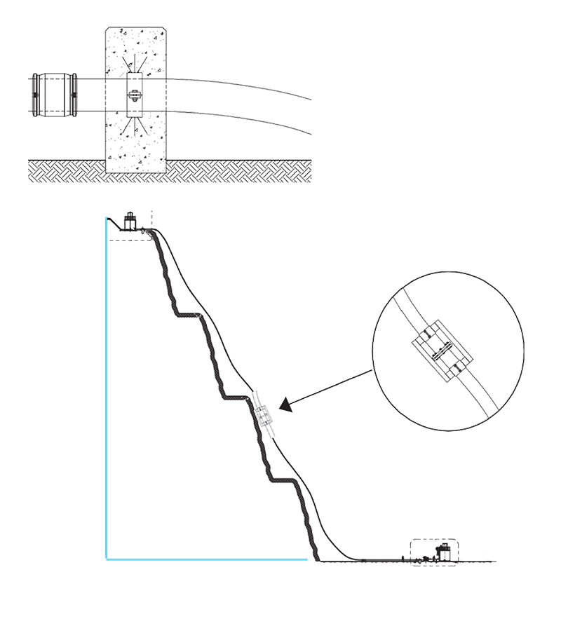
Securing inclined Pexgol pipes
The top and bottom ends of the Pexgol pipeline should be anchored by a fixpoint (See drawing).
The Pexgol pipeline can be laid uphill or downhill in a long continuous section, without any fixpoint between the top and bottom ends.
There is no limitation on the total pipe length.
It is recommended to design the pipe with an additional 1-2% slack in order to reduce potential axial contraction forces.
The weight of the pipe might increase due to accumulation of soil or snow on top of it. This additional weight will be balanced by the increasing friction between the pipe and the ground.

Restraining of fittings along the pipeline
In slopes of less than 40°, all mechanical couplers (flared ends, flanged couplers etc.) should be restrained by floating Fixpoint devices like Golan’s Fixpoint Bridge.
Electrofusion couplers can be installed without a floating Fixpoint device.
In slopes above 40°, all type of fittings (including electrofusion couplers) should be restrained by floating Fixpoint devices.
When installing a repair fitting, the pipe can be secured by a fixpoint bridge prior to cutting the pipe.